J36 like RCS perview P2 Aboserbing(类J36RCS预览P2 吸波 )
The effect of absorbing material is important, but it is not like an average military fan; all you need is just talk. No matter how many cool names are in there, it won’t change a thing.
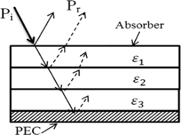
First of all, what is a radar absorbing structure? In a nutshell, it is a structure that creates a smooth transitional medium between free space and the object. Due to radio waves don’t care about anything relatively small compared to the wavelength, such a structure can make a smooth transition by changing the empty ratio.
Other designs are equivalent to such a structure, the most common of which is a multi-layer absorbing. By changing the properties of each layer to create a smooth transition.
Such kind of idea cannot only be used for absorbing material. For example, in this case, I want to reduce the RCS of such a wiring. I can use the same idea to curve the wire, and it effectively reduces the peak RCS in the resonance frequency.
Here I am using a multi-layer absorber to build an absorber structure. What makes it good is that, in this case, all you need to do is change the absorber’s parameter, but you don’t need to change the model, and it automatically covers the entire aircraft.
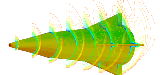
In this case, I am using the AN74 absorber as a basis. Changing each layer’s parameter to be equivalent to any thickness absorbing structure. And the simulation has been running at 12GHz horizontal polarized.
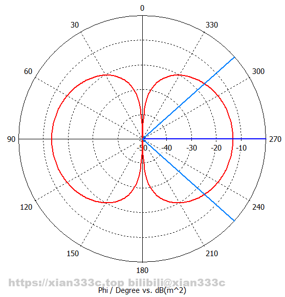
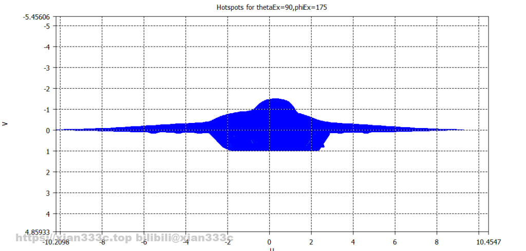
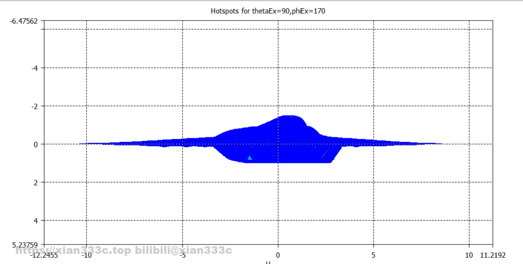
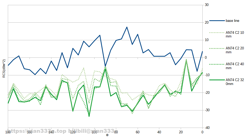
Φ=180 is where the nose is heading, and Φ=0 is the tail
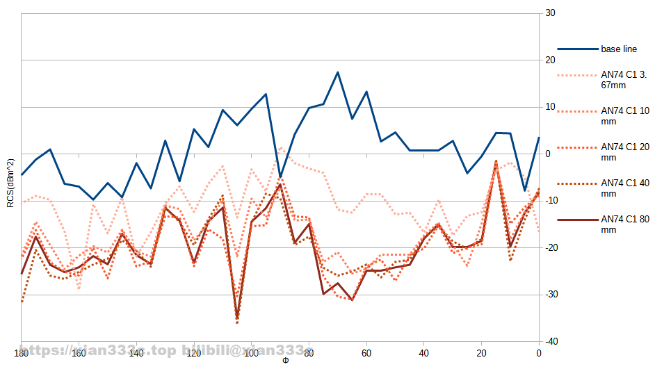
You can see that the structure has been made thicker, but the RCS has been stopped from reducing once it reaches 40mm(4cm). It looks like a lot of frontal RCS has been produced by the intake edge. Though when Absorbing wasn’t used, it looks like also a lot of RCS was produced by the intake camber and the engine. Once it reached broadside, also IR pod also creates some RCS.
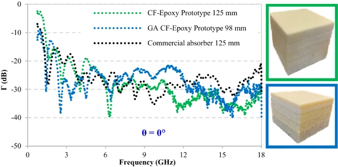
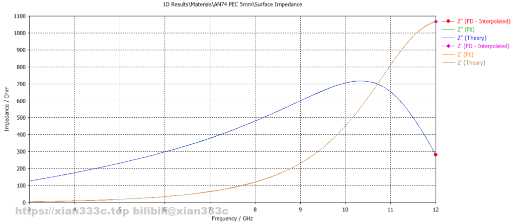
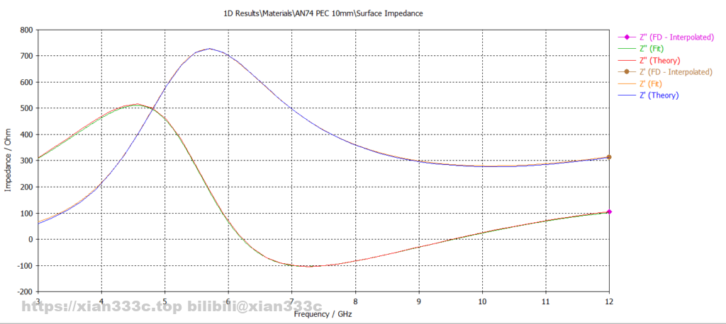
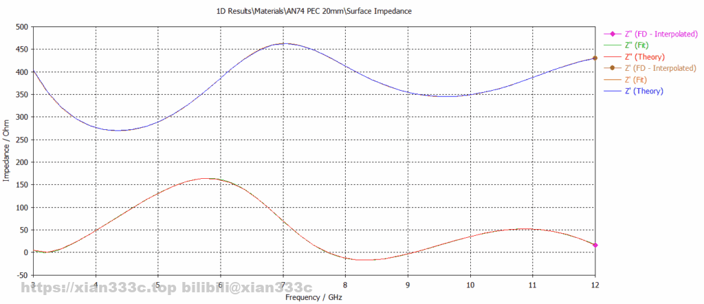
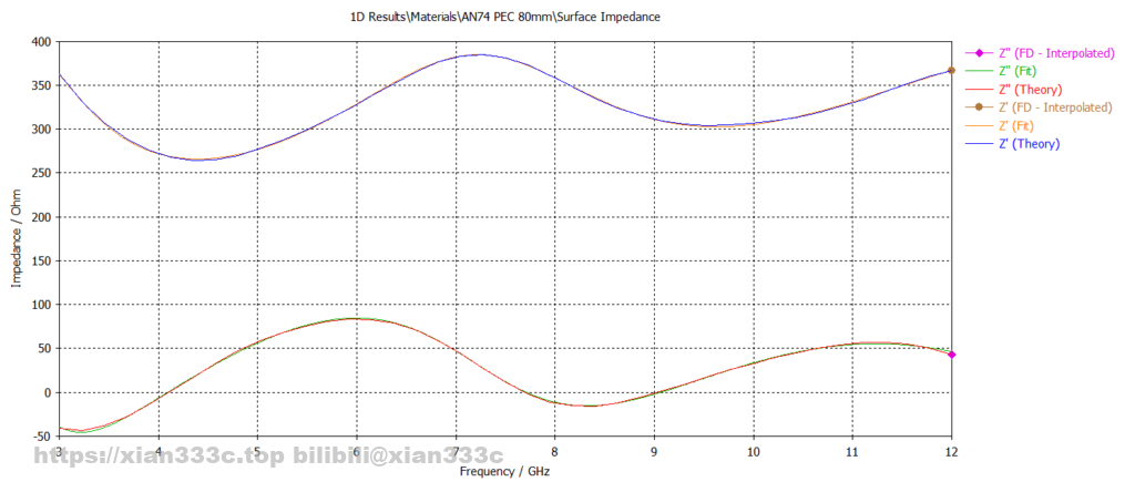
Such phenomena can be seen by material impedance. When thickness goes on, impedance shows in a small range, and is very similar between 20mm and 80mm.
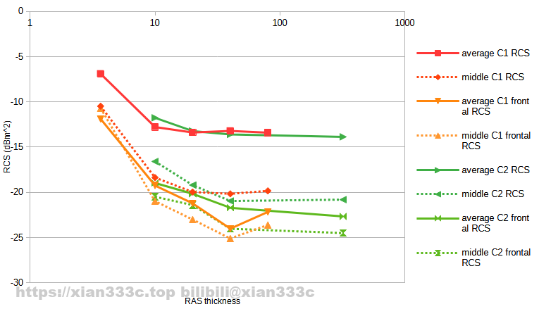
AN74 may not have the best transition. In this case, I can use more layers with a designed thickness of each layer to create a better transition structure. And also, I make the structure as big as 32cm. But as a result is very similar.
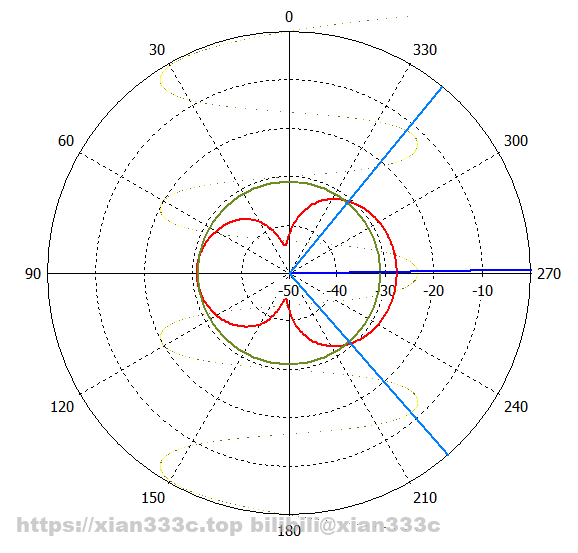
With such an absorption, in its limits, J36 likes can reach RCS of between -20~-30 dBm^2. Due to it being applied to the entire plane in real life, it will be impractical.
Compares average and median RCS in all and frontal directions.
To show the effectiveness of absorption, here is compared to baseline RCS. It structure absorbed around -20dB of radar waves.

To reduce RCS, the limits are more like in the material itself rather than the structure. And even if you directly use absorbing material only to make a plane, there is still more likely of hitting the limits.
But just by the numbers, it doesn’t mean there is no way to reach a lower figure.

I just reached a lower number. For a similar reason, even for some stuff like the J20 model, different people still get different numbers. Typical stealth fighter with PEC will get slightly higher than -10 dBm^2, one of the reasons is that intake with multiple reflections will let the engine make greater RCS. But in this article people get results much lower, even in the frontal there are many places reached -40 dBm^2.

The answer is quite simple: the author used the PO method to calculate RCS. Despite it being a normal as military code. But PO doesn’t have a model like PTD for diffraction and doesn’t calculate reflection.
I did the same to my lower-number result; I disabled reflection, and PTD makes it closer to the PO method. Of course, it is not good. But funny enough, most stealth projects due to their long development cycle, are designed in such method. F117 is the first designed in the PO method.
Normally, when you think about such kind thing first you should be thinking about stuff like solver and setting, and parameters in there. Just like doing CFD, if you really know about it. You should be thinking about meshing, domain, boundary layer mesh, and stuff like parameters for turbulent model rather than 3d models.